Some experiments
AF amplifier to interface with diode product detector
Circuits from EMRFD were used to make the AF amplifier with SSB filter.
gnucap simulator was used to get some idea of circuit behaviour before actual construction.
gnucap simulator was used to get some idea of circuit behaviour before actual construction.
Here is the circuit that was simulated. Dotted lines indicate how PD is connected to AF amplifier.

Files used for simulation ..................
*** filename BC547B.MOD ***
.MODEL BC547B NPN(
+ IS=2.39E-14
+ NF=1.008
+ ISE=3.545E-15
+ NE=1.541
+ BF=294.3
+ IKF=0.1357
+ VAF=63.2
+ NR=1.004
+ ISC=6.272E-14
+ NC=1.243
+ BR=7.946
+ IKR=0.1144
+ VAR=25.9
+ RB=1
+ IRB=1E-06
+ RBM=1
+ RE=0.4683
+ RC=0.85
+ XTB=0
+ EG=1.11
+ XTI=3
+ CJE=1.358E-11
+ VJE=0.65
+ MJE=0.3279
+ TF=4.391E-10
+ XTF=120
+ VTF=2.643
+ ITF=0.7495
+ PTF=0
+ CJC=3.728E-12
+ VJC=0.3997
+ MJC=0.2955
+ XCJC=0.6193
+ TR=1E-32
+ CJS=0
+ VJS=0.75
+ MJS=0.333
+ FC=0.9579 )
*********************
**************** filename rxAF.cir ****************
AF pre-amplifier after product detector
* Desired input impedance = 50 Ohm at audio to 20 Mhz
* With passive SSB filter
* file-name rxAF.cir
Vin in 0 generator(1m)
.gen freq=2K
Vcc 8 0 DC=12 AC=0
.include ./BC547B.MOD
Q1 5 6 7 BC547B
Q2 8 9 4 BC547B
Q3 11 5 12 BC547B
Rin in 1 50
R1 2 0 50
R2 4 5 6.8k
R3 7 0 2.7k
R4 4 6 10k
R5 6 0 3.3k
R6 8 9 47k
R7 8 10 1k
R8 10 11 680
R9 12 0 4.7k
R10 12 13 100
C1a 1 2 470n
C1b 1 2 100n
C2 3 0 100n
C3 3 7 47u
C4 6 0 47u
C5 9 0 22u
C6 10 0 47u
C7 11 14 220n
C8 13 0 22u
L1 1 3 1.3m
Q4 16 17 18 BC547B
Q5 20 16 21 BC547B
R11 14 0 10k
R12 8 15 100
R13 15 17 6.8k
R14 17 0 6.8k
R15 15 16 470
R16 18 0 1k
R17 18 19 390
R18 15 20 100
R19 21 0 1000
R20 22 23 140
R21 24 25 140
*R20 22 23 10 Better inductor!
*R21 24 25 10 Better inductor!
C9 14 17 220n
C10 15 0 220u
C11 20 0 220u
C12 19 0 10u
C13 21 22 100u
C14 21 0 10u
C15 24 0 100n
C16 26 0 22n
C17 22 24 10n
C18 24 26 22n
C19 16 17 1n
L2 23 24 47m
L3 25 26 47m
RL 26 0 1000
*** dc measurements ***
.print dc v(8) v(4) v(5) v(11)
.dc
.print dc v(15) v(16) v(18) v(21)
.dc
.print dc ic(Q1) ic(Q2) ic(Q3) ic(Q4) ic(Q5)
.dc
*.print dc ib(Q2) ie(Q2)
*.dc
*.print dc ib(Q3) ie(Q3)
*.dc
*.print dc ib(Q4) ie(Q4)
*.dc
*.print dc ib(Q5) ie(Q5)
*.dc
*** AC voltages at some nodes for 1.5 kHz input ***
.print op v(in) v(1) v(22) v(26)
.print ac v(in) v(1) v(22) v(26)
.ac 1.5e3
* R17 ( 390R ) can be made smaller ( 47R ?) to get more gain
*** Input impedance at different frequencies ***
.print op z(1)
.print ac z(1)
.ac 0 20e6 10000 > zinHi
.ac 0 10e3 100 > zinLo
*** frequency response
.print op v(26) vdb(26)
.print ac v(26) vdb(26)
.ac 10 1k 5 > frLo
.ac 100 10k 10 > frHi
*** Wave shape ***
*.print tran v(1) v(26)
*.tran 2m 3m 5u > ws
* To view wave shape uncomment above two line; takes time!
* Next line takes looonnggeer time!!
*.tran 30m 31m 5u > ws
.end
All are comments after the above line
Simulate with.......
$ gnucap -b rxAF.cir
..
..
..
AF preamplifier after product detector
# v(8) v(4) v(5) v(11)
0. 12. 11.08 5.7555 10.177
# v(15) v(16) v(18) v(21)
0. 10.68 8.5093 4.6067 7.8129
# ic(Q1) ic(Q2) ic(Q3) ic(Q4) ic(Q5)
0. 779.47u 0.0016111 0.001085 0.0045908 0.0077847
#Freq v(in) v(1) v(22) v(26)
$ gnuplot
..
..
gnuplot> set style data lines
Input impedance....
gnuplot> plot "zinLo"
gnuplot> plot "zinHi"
Frequency response at node 26....
gnuplot> plot "frLo" using 1:2
gnuplot> plot "frLo" using 1:3
gnuplot> plot "frHi" using 1:2
gnuplot> plot "frHi" using 1:3
*********************************************************************************
Input impedance up to 10 KHz.........
gnuplot> set title "Zin of AF amplifier up to 10 kHz"
gnuplot> set xlabel "Hertz"
gnuplot> set ylabel "Ohms"
gnuplot> plot "ZinLo" using 1:2 with lines
Input impedance up to 20MHz...........
gnuplot> reset
gnuplot> set title "Zin of AF amplifier up to 20 MHz"
gnuplot> set ylabel "Ohms"
gnuplot> set xlabel "Hertz"
gnuplot> plot "zinHi" using 1:2 with lines
Simulator indicated that AF port of product detector is terminated by nearly 50 Ohms.
Frequency response of AF filter up to 1KHz
Frequency response up to 10KHz
Frequency response becomes more meaningful when output is expressed in VdB.......
Winding resistance of small 47 mH inductors are 140 Ohms. Good inductors with lower winding
resistance would produce more attenuation of unwanted frequencies.
The AF preamplifier appeared to be usable based on simulated results.
The circuit was made using ugly construction ( Manhattan variant! ) using thin galvanised iron
as base plate. AF power amplifier is LM386 based.
Circuit was tested with a B.Obama speech playing on a mobile phone. Distortion was present
but it was tolerable.
A 9.999 MHz signal, from a AD9850 based DDS, at the IF port of PD produced a strong tone in loudspeaker.
This is the LM386 speaker driver.

Files used for simulation ..................
*** filename BC547B.MOD ***
.MODEL BC547B NPN(
+ IS=2.39E-14
+ NF=1.008
+ ISE=3.545E-15
+ NE=1.541
+ BF=294.3
+ IKF=0.1357
+ VAF=63.2
+ NR=1.004
+ ISC=6.272E-14
+ NC=1.243
+ BR=7.946
+ IKR=0.1144
+ VAR=25.9
+ RB=1
+ IRB=1E-06
+ RBM=1
+ RE=0.4683
+ RC=0.85
+ XTB=0
+ EG=1.11
+ XTI=3
+ CJE=1.358E-11
+ VJE=0.65
+ MJE=0.3279
+ TF=4.391E-10
+ XTF=120
+ VTF=2.643
+ ITF=0.7495
+ PTF=0
+ CJC=3.728E-12
+ VJC=0.3997
+ MJC=0.2955
+ XCJC=0.6193
+ TR=1E-32
+ CJS=0
+ VJS=0.75
+ MJS=0.333
+ FC=0.9579 )
*********************
**************** filename rxAF.cir ****************
AF pre-amplifier after product detector
* Desired input impedance = 50 Ohm at audio to 20 Mhz
* With passive SSB filter
* file-name rxAF.cir
Vin in 0 generator(1m)
.gen freq=2K
Vcc 8 0 DC=12 AC=0
.include ./BC547B.MOD
Q1 5 6 7 BC547B
Q2 8 9 4 BC547B
Q3 11 5 12 BC547B
Rin in 1 50
R1 2 0 50
R2 4 5 6.8k
R3 7 0 2.7k
R4 4 6 10k
R5 6 0 3.3k
R6 8 9 47k
R7 8 10 1k
R8 10 11 680
R9 12 0 4.7k
R10 12 13 100
C1a 1 2 470n
C1b 1 2 100n
C2 3 0 100n
C3 3 7 47u
C4 6 0 47u
C5 9 0 22u
C6 10 0 47u
C7 11 14 220n
C8 13 0 22u
L1 1 3 1.3m
Q4 16 17 18 BC547B
Q5 20 16 21 BC547B
R11 14 0 10k
R12 8 15 100
R13 15 17 6.8k
R14 17 0 6.8k
R15 15 16 470
R16 18 0 1k
R17 18 19 390
R18 15 20 100
R19 21 0 1000
R20 22 23 140
R21 24 25 140
*R20 22 23 10 Better inductor!
*R21 24 25 10 Better inductor!
C9 14 17 220n
C10 15 0 220u
C11 20 0 220u
C12 19 0 10u
C13 21 22 100u
C14 21 0 10u
C15 24 0 100n
C16 26 0 22n
C17 22 24 10n
C18 24 26 22n
C19 16 17 1n
L2 23 24 47m
L3 25 26 47m
RL 26 0 1000
*** dc measurements ***
.print dc v(8) v(4) v(5) v(11)
.dc
.print dc v(15) v(16) v(18) v(21)
.dc
.print dc ic(Q1) ic(Q2) ic(Q3) ic(Q4) ic(Q5)
.dc
*.print dc ib(Q2) ie(Q2)
*.dc
*.print dc ib(Q3) ie(Q3)
*.dc
*.print dc ib(Q4) ie(Q4)
*.dc
*.print dc ib(Q5) ie(Q5)
*.dc
*** AC voltages at some nodes for 1.5 kHz input ***
.print op v(in) v(1) v(22) v(26)
.print ac v(in) v(1) v(22) v(26)
.ac 1.5e3
* R17 ( 390R ) can be made smaller ( 47R ?) to get more gain
*** Input impedance at different frequencies ***
.print op z(1)
.print ac z(1)
.ac 0 20e6 10000 > zinHi
.ac 0 10e3 100 > zinLo
*** frequency response
.print op v(26) vdb(26)
.print ac v(26) vdb(26)
.ac 10 1k 5 > frLo
.ac 100 10k 10 > frHi
*** Wave shape ***
*.print tran v(1) v(26)
*.tran 2m 3m 5u > ws
* To view wave shape uncomment above two line; takes time!
* Next line takes looonnggeer time!!
*.tran 30m 31m 5u > ws
.end
All are comments after the above line
Simulate with.......
$ gnucap -b rxAF.cir
..
..
..
AF preamplifier after product detector
# v(8) v(4) v(5) v(11)
0. 12. 11.08 5.7555 10.177
# v(15) v(16) v(18) v(21)
0. 10.68 8.5093 4.6067 7.8129
# ic(Q1) ic(Q2) ic(Q3) ic(Q4) ic(Q5)
0. 779.47u 0.0016111 0.001085 0.0045908 0.0077847
#Freq v(in) v(1) v(22) v(26)
1.5K 0.001 418.1u 0.38732 0.34967
$ gnuplot
..
..
gnuplot> set style data lines
Input impedance....
gnuplot> plot "zinLo"
gnuplot> plot "zinHi"
Frequency response at node 26....
gnuplot> plot "frLo" using 1:2
gnuplot> plot "frLo" using 1:3
gnuplot> plot "frHi" using 1:2
gnuplot> plot "frHi" using 1:3
*********************************************************************************
Input impedance up to 10 KHz.........
gnuplot> set title "Zin of AF amplifier up to 10 kHz"
gnuplot> set xlabel "Hertz"
gnuplot> set ylabel "Ohms"
gnuplot> plot "ZinLo" using 1:2 with lines
Input impedance up to 20MHz...........
gnuplot> reset
gnuplot> set title "Zin of AF amplifier up to 20 MHz"
gnuplot> set ylabel "Ohms"
gnuplot> set xlabel "Hertz"
gnuplot> plot "zinHi" using 1:2 with lines
Simulator indicated that AF port of product detector is terminated by nearly 50 Ohms.
Frequency response of AF filter up to 1KHz
Frequency response up to 10KHz
Frequency response becomes more meaningful when output is expressed in VdB.......
Winding resistance of small 47 mH inductors are 140 Ohms. Good inductors with lower winding
resistance would produce more attenuation of unwanted frequencies.
The AF preamplifier appeared to be usable based on simulated results.
The circuit was made using ugly construction ( Manhattan variant! ) using thin galvanised iron
as base plate. AF power amplifier is LM386 based.
Circuit was tested with a B.Obama speech playing on a mobile phone. Distortion was present
but it was tolerable.
A 9.999 MHz signal, from a AD9850 based DDS, at the IF port of PD produced a strong tone in loudspeaker.
This is the LM386 speaker driver.
 |
| Interconnection between AF preamplifier and speaker driver |
This picture shows Product Detector, AF preamplifier and LM386 speaker driver.
 |
| PD on left showing BFO, AF and IF ports. AF amp. on right |
Though it looks like something the cat dragged in, it worked in a simple receiver.
This picture shows a simple receiver.

When antenna, VFO and 12 Volt were connected, reception was possible on some bands.
Received on VFO frequency Mode Remarks
MHz MHz
7.074 17.073000 FT8 Poor and unusable
7.145 2.948650 LSB Poor and unusable
10.136 20.135600 FT8 Poor and unusable
14.074 24.073000 FT8 Usable
18.100 28.098000 FT8 Usable
21.074 31.073100 FT8 Usable
24.914 34.914000 FT8 Usable
28.074 38.073100 FT8 Usable
Here is a screenshot of 20M FT8 reception..

IF amplifiers with 10 MHz crystal filter in between.
Tried to do these....
50 Ohm termination to mixer,
A strong post mixer amplifier with 16 mA in each of Q1 and Q2,
50 Ohm termination to product detector,
500 Ohm termination at both ends of XTAL filter,
Minimum change of impedance when gain is changed.
Don't know what ended up with 😟
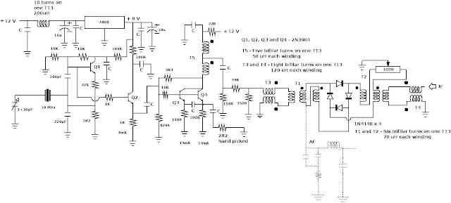
Schematic of BFO and Product Detector.

Schematic of VFO amplifier and Mixer.
 |
| VFO amplifier and Mixer |
9th Aug. 2020
Swapping input and output of a 10 MHz IF amplifier
The IF amplifier can be used in TX and RX modes when IN and OUT are swapped. Gain in TX mode
is to be reduced.
Tried to implement this block diagram.
1N4148 diodes are used as series switches. Capacitance of nonconducting diodes, however small,
can provide a path from OUT to IN and cause oscillation. 2N3904 transistors are used as shunt switches
to ground the feedback signal.
Implementation............
Now PD works also as Balanced Modulator. RX mixer also works as TX mixer.
Reception on the simple receiver was as before without oscillation. Reception stopped when PTT
was pressed. Testing of the TX path was not carried out. A large carrier leak was detected on TX😞
To be continued.....
VU2NIL
9th Aug 2020


Comments
Post a Comment