Direct Conversion Receiver using sub-harmonic mixer
Used this sub-harmonic mixer, popularised by Vladimir Polyakov (RA3AAE), to make a 40M direct conversion receiver.


Circuits on the power supply board:


 |
| Sub-harmonic mixer |
Example: Local oscillator is set to 3572.5 kHz to receive 7145 kHz in this sub-harmonic mixer.
LO leakage to antenna causes most problems in direct conversion receivers. Anticipated little
problem because LO and Rx frequencies are different in a sub-harmonic mixer.
Tried a single tuned front end without RF amplifier, DDS VFO as LO, a simple 12 Volt power
supply and audio amplifier. Audio amplifier was followed by a LM386 speaker amplifier.
Result was an unusable radio with strong hum. 2nd harmonic of LO was reaching the antenna
or the power supply had ripple ?
Assumed both and applied Grandma-approved home remedies.
- RFC with ferrite core, bypassed with 100nF ceramic disc capacitor, in every conceivable point
- 10000uF capacitor after rectifiers of power supply
- 18 Volt from first regulator, goes to radio box through RF filter
- 18 volt is input to a an active ripple filter via another RF filter
- Input to 12 Volt regulator goes from ripple filter
- LO passes through LPF with a trap at 7MHz
- RF amplifier,sub-harmonic mixer,LO buffer,AF amplifier,active ripple filter,and 12 Volt regulator are put inside an aluminium box ( locally sold as cash box ). LM386 speaker amplifier was kept outside the box.
- Noise filter on 230 VAC power line
- 10nF ceramic capacitors were put across each rectifier and secondary windingof power transformer.
Almost all circuits came from EMRFD. Made little modifications to meet local needs.
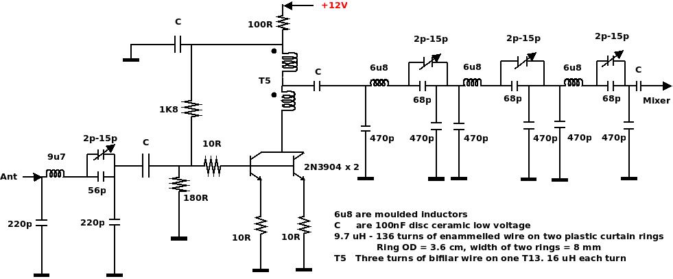
Circuit of DCRX

POLO mint-sized ferrite cores are available locally, called T13 by component retailers. No specifications are available. T13 are cheap and good as RFC core.
Resistance between opposite sides of T13 varies fron 2K5 to 60K 😞.
Can be harvested from dead CFL.
T13 were used instead of FT-37-43 ( don't have any)

Speaker amplifier:

40M rf amplifier was made on a separate board.
Circuit of the 40M rf amplifier..

Power supply schematic:

 |
| Power line filter |
 |
The receiver was picking up some FT8 and local LSB SSB signals.
There were no hum and whistles but it was noisy.
Two short recorded (20th Aug 2021) QSO can be downloaded/played.
Filenames indicate LO in kHz.
Going to add a low pass filter to cut some noise.
73 Basanta, VU2NIL
3rd Oct. 2019
Rummaged through junk boxes and stock of components for capacitors and inductors to make a filter. Failed to find suitable inductors.
At this point developed an itch to make the low pass filter with Digital Signal Processing. But my knowledge of DSP is zero. Looked around and found gnuradio-companion.
One can create GNU Radio flow graphs with this; the end result may not be as expected 😀
Thank you GNU Radio Team.
Looked around some more, found excellent tutorials. However most of what they explained
was way above my head.
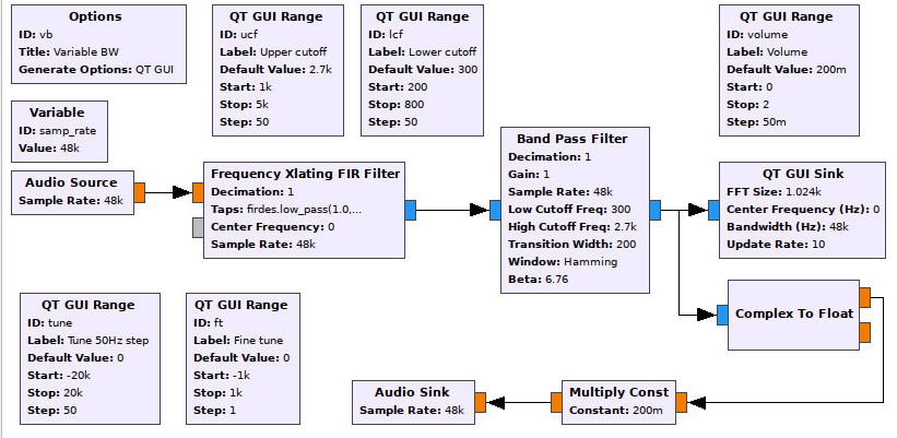
Went ahead anyway to make my filter and created a few flow graphs, without a clue of what is taking place under the hood. Kept one flow graphs out of these; vb.grc.


vb.grc worked after a fashion 😔
vb.grc can be downloaded from here.
When Raspberry Pi 4B arrived, Paspberry Pi 3B+ took its place on the shelf doing nothing. It was used once as a WSPR transmitter. Wanted to use it to make the low pass filter.
Using a Paspberry Pi 3B+ to make a filter is definitely not cost effective but it came in handy for my introduction to GNU Radio.
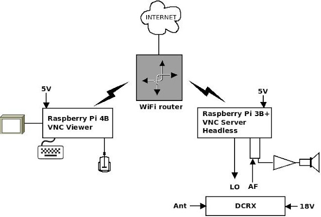
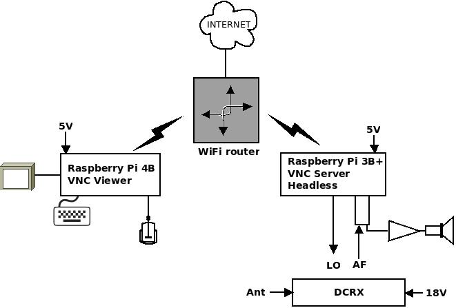
Proposed set-up:
- Raspberry Pi 3B+ would run GNU Radio
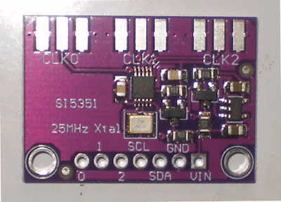
- Raspberry Pi 3B+ would generate LO
- One cheap USB sound card for AF in and AF out
- Raspberry Pi 3B+ would run headless; controlled by Raspberry Pi 4
- Headphone out of USB sound card could drive a regular PC speaker amplifier or LM386 speaker amplifier
- Raspberry Pi 3B+ was fixed on the power supply board; a better place would be lid of the aluminium box, on the outside.


Setup of pi4 and pi3:
RaspberryPi 3B+ setup :
2021-05-07-raspios-buster-armhf.zip ( the OS ) was installed on a 16 GB micro SD card.
Prepared SD card was put into Raspberry Pi 3B+ and booted up.
pi@raspberrypi:~ $ sudo raspi-config
Country, language, keyboard, WiFi country, WiFi ssid and password were set.
Hostname was changed to pi3, VNC server was enabled. Auto login of user pi was
not disabled.
Restarted pi3.
pi3 connected to network through wireless router.
System was made up to date
pi@pi3:~ $ sudo apt update
pi@pi3:~ $ sudo apt upgrade
Installed synaptic....
pi@pi3:~ $ sudo apt install synaptic
Started synaptic...
gnuradio, fldigi and pavucontrol-qt were installed.
Exited synaptic.
WSJTX installation..
pi@pi3:~/Downloads $ sudo dpkg -i ./wsjtx_2.4.0_armhf.deb
Selecting previously unselected package wsjtx.
(Reading database ... 134928 files and directories currently installed.)
Preparing to unpack ./wsjtx_2.4.0_armhf.deb ...
Unpacking wsjtx (2.4.0) ...
dpkg: dependency problems prevent configuration of wsjtx:
.
.
.
pi@pi3:~/Downloads $ sudo synaptic
broken package was fixed, missing dependencies were
installed.
Exited synaptic.
Again ran this command...
pi@pi3:~/Downloads $ sudo dpkg -i ./wsjtx_2.4.0_armhf.deb
This time wsjtx_2.4.0 was installed.
pi@pi3:~ $ ifconfig
wlan0 address was 192.168.29.252
This was noted down for using VNC viewer from Paspberry Pi4.
Before using VNC viewer from pi4, this command is used to check the address of pi3
pi@pi4:~ $ nmap -p 5900 192.168.29.0/24
Edited output....
Nmap scan report for 192.168.29.252
Host is up (0.50s latency).
PORT STATE SERVICE
5900/tcp open vnc
Nmap done: 256 IP addresses (5 hosts up) scanned in 24.32 seconds
Setup for Local Oscillator:
WsprryPi would be used generate LO
pi@pi3:~ $ sudo apt install git
pi@pi3:~ $ git clone https://github.com/JamesP6000/WsprryPi
Cloning into 'WsprryPi'...
remote: Enumerating objects: 350, done.
remote: Total 350 (delta 0), reused 0 (delta 0), pack-reused 350
Receiving objects: 100% (350/350), 193.54 KiB | 381.00 KiB/s, done.
Resolving deltas: 100% (181/181), done
pi@pi3:~ $ cd WsprryPi/
pi@pi3:~/WsprryPi $ less README
pi@pi3:~/WsprryPi $ make
There was an error
/usr/bin/ld: mailbox.c:(.text+0xcbc): undefined reference to `makedev'
The header <sys/sysmacros.h> was included in file mailbox.c
pi@pi3:~/WsprryPi $ make
Compiled without error but with warnings!
Installed anyway.
pi@i3:~/WsprryPi $ sudo make install
Example:
This command sets LO to receive 7074000 Hz (FT8)
pi@pi3:~ $ sudo wspr -t 3537000
When wspr is running, if any window in pi3 is moved or resized, pi3 hangs.
Could not get around it 😞
FT8 reception:
FT8 signal can be received without using a GNU radio flow graph. No filter is used
in this case. Audio input of wsjtx is to be set as microphone input of sound card.
Then audio input of wsjtx was set as sound card output. In this case a GNU radio flow graph was used. Latency of Raspberry Pi 3B+ showed up as an increase in value of DT.
This video shows FT8 reception.
To reduce size of video file some functions were started on pi3 desktop with a previous session of VNC viewer.
These were a text terminal, volume control and wsjtx.
WsprryPi is not a VFO. In the flow graph tuning was tried but it was not very effective; mainly due to latency of pi3 and to some extent, limited high frequency response of audio amplifier.
To test tuning and SSB/LSB reception, LO was set at 3564000 ( 7.128 MHz ).
A net operates on 7.145 MHz in the morning.
SSB/LSB could be received when tuning was set at -17 kHz.
Another net operates on 7.11 MHz.
No signal was there when tuning was set at +18 kHz. Going to try another time when the band condition is better .
This video was recorded on 3rd Oct. 2021
73 ... Basanta
Thanks for this information
ReplyDeleteDipak (vu3okt)