150 watt 40m amplifier
My plastic (air) core transformer looks like this...
 |
| An air core transformer |
This amplifier is used with IC-718 on 40m. Power output drops steeply with increasing frequency.
It is unusable at 20m 😔
In this experiment four IRFP450 are used in the final stage to get at least 150 Watts on 40m.
Another IRFP450 is used as driver.
Here is the circuit.........

R1 ... R16 are paralleled to increase wattage rating. Paralleled resistors are drawn with thicker lines. Values of the resistors are shown on the schematic and are also repeated here.
R1 = 3 || 470R/2W = 156R6/6W
R2 = 3 || 470R/2W = 156R6/6W
R3 = 4 || 150R/2W = 37R5/8W
R4 = 3 || 3R3/2W = 1R1/6W
R5 = 4 || 22R/2W = 5R5/8W
R6 = 4 || 22R/2W = 5R5/8W
R7 = 4 || 22R/2W = 5R5/8W
R8 = 4 || 22R/2W = 5R5/8W
R9 = 2 || 22R/2W = 11R/4W
R10 = 2 || 22R/2W = 11R/4W
R11 = 2 || 22R/2W = 11R/4W
R12 = 2 || 22R/2W = 11R/4W
R13 = 9 || 10R/2W = 1R1/18W
R14 = 9 || 10R/2W = 1R1/18W
R15 = 9 || 10R/2W = 1R1/18W
R16 = 9 || 10R/2W = 1R1/18W
T13 are small ferrite toroids of obscure specifications.
This is the control circuit ( Carrier detect, relay driver, bias and cooling fan ) ...

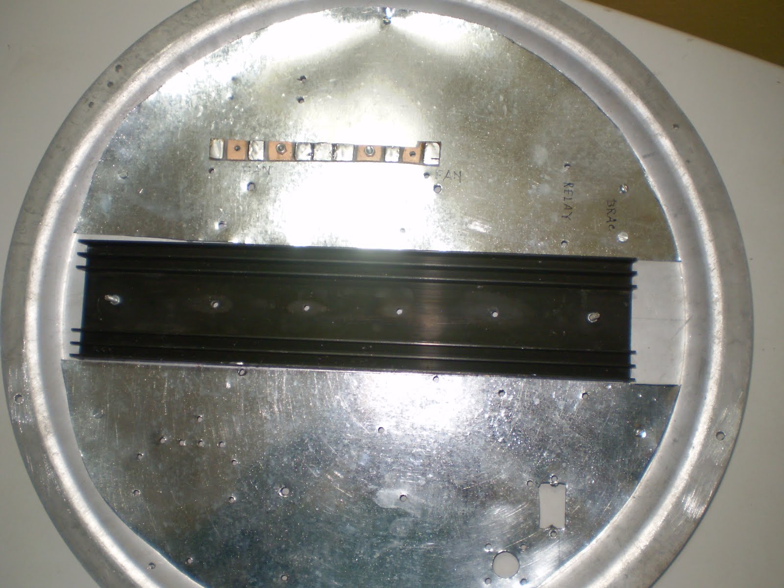
The amplifier is built on the lid of a 14 inch diameter aluminium pot.
 |
| Lid bottom |
 |
| Lid top |
The lid acts as heat spreader, Copper foil is used as ground for some portion of the circuit. It spreads heat from power transistors to the aluminium lid.
Heatsink is fixed on top of lid. Rest of the lid is
covered with thin GI sheet. Ground end of components are soldered to this GI sheet.
 |
| Components on top of lid |
 |
| Components on bottom of lid
T1 is a conventional transformer made with two 3.5 cm copper tubes and 4 T13 toroids,
two on each leg.
|

Two tubes are shorted at one end with a 3 cm piece of glass epoxy PCB. One free end of the lower
tube is connected to ground. The other free end is connected to gate of driver with a ceramic
capacitor. The primary has two turns of Teflon insulated wire. Sleeves are slipped inside the
tubes to prevent chaffing of the wire.
Inductance between two open ends of cu-tubes = 5.5 uH.
Inductance of two turn primary = 20 uH
RFC in drain of Q1 ( IRFP450 ) is made on a plastic toroid. The toroid is made with two short pieces of plastic water pipe.
 |
| RFC1 former |
One 3 cm piece of white plastic water pipe of 1.5 inch ID and one 3 cm piece of white plastic water pipe of 1 inch ID were used to make the toroid. Holes were drilled in the pipe pieces to reduce loss.The smaller diameter pipe was put inside the larger diameter pipe and fixed together with hot glue.
36 turns of single layer spaced winding produced about 8.6 uH.
Conventional transformers are used to drive the four gates of Q2, Q3, Q4 and Q5.

Two 3.5 cm copper tubes of 5 mm OD were used.
A 1 cm x 3 cm piece of PCB is used to short one end of two tubes. Six T13 cores are used for each transformer, three on each leg.
Primary has two turns of Teflon insulated wire.
Inductance between two open ends of cu-tubes = 8 uH.
Inductance of two turn primary = 30 uH
The drain transformers, T4 / T5 of the push-pull stages use similar 3 cm plastic pipe sections
used for RFC1 construction. The smaller diameter pipe was put inside the larger diameter pipe
and fixed together with hot glue, with one side touching.
 |
| T4/T5-a |
 |
| T4/T5-b |
 |
| T4/T5-c |
 |
| T4/T5-d |

Winding has 29 spaced turns with Teflon bifilar ( black and red ) wire. Odd number of turns are used to take a centre-tap on red wire. Drain DC power is connected to the centre-tap.
Inductance of each winding is about 6 uH average.
Standing current in all five IRFP450 is set at 300 mA.
Voltage developed on secondary of T4 and T5 buck or aid each other depending on sense of winding.
The ends of T4 secondary were changed to put secondaries in series aiding.
Output was not zero when they were bucking, So the output is not maximum when in series aiding.
Failed to figure out how to set the two secondary voltages in exact phase.
The amplifier is powered by a simple unregulated power supply of about 75 Volts.
Power output is measured with HB dummy load fitted with RF probe.
Four 200W/230V metal filament lamps are sometimes used for current limiting; mainly during testing.
No current limiting with lamps are used to get more power output.
73 ........ VU2NIL

Comments
Post a Comment